News:

Forum may be experiencing issues.

Main Menu
Menu

Show posts

This section allows you to view all posts made by this member. Note that you can only see posts made in areas you currently have access to.

Show posts Menu

Topics - Cybercow

#1
Build Reports / MadBean Zombii Fuzz Build
January 20, 2024, 10:55:36 AM
MadBean did a fine job on the Zombie Fuzz - a tweaked Fuzz Factory with some fun additions. The included faceplate has space for a couple of SMD LEDs beneath transparent pots with wiring points dramatically close to the bypass LED. Admittedly, wiring up the faceplate was a challenge - but challenge accepted. With the added toggles, one to bypass a short tone stack and one to change the feedback resistance between the two Ge BJTs, this thing has some real ballz. And tho the build specifies a 1590BS (deeper 1590B) or 125B enclosure, I was able to get it all squoze into a 1590B.

Anyway, enough talk . . . .  on to the build pics . . . .
#2
Did up my first VFE DragonHound with a VFE SB V3 switching board and find that it's ALWAYS in bypass. I pre-measured EVERY component before soldering it into place, so I know the values are all correct.

I know the switching board is working (except I've yet to verify the TQ2-L-5V relay) because the LED indicates whether or not it is bypass or engaged - AND - the dual-mode momentary-on option (tap-tap-hold) works inactivating or deactivating the dual-mode option.

With the unit powered up and engaged or in bypass, the input and output jacks are always shorted together.

I suspect the TQ2-L-5V. But I got them from Mouser. So the reliability of a known good relay is high. I have 9.2v at the SB V3 supply input with ~-4.5v and ~+5v at the - and + points between the two boards.

Any leads, options or something I may have missed?
#3
Dual-Chorus 2 (Mini-Me x2 plus max mods)

With all the known mods available on this pair of Mini-Me circuits, plus an "LFO Sync" mod, this dual chorus is a delightful motion-wave machine. Based originally from the Small Clone, Barry's take on this classic chorus circuit does exceedingly well to capture and deliver a good strong chorus effect. The mods just add to the glory.

With two chorus circuits, this pedal can be wired for:
1. Mono-In to Mono-Out for the two circuits to work in series.
2. Mono-In to Stereo-Out (individual L/R mono-outs) for parallel operation.
3. Stereo-In (individual L/R mono-ins) to Stereo-Out (individual L/R mono-outs) for parallel operation.
4. Use either circuit by itself.

The mods are as a follows:
1. Depth Range extender – swaps out C18 with 3 different cap values. (Reaches into flanger territory.)
2. Rate Range – adds another 2µ2 cap to C21 to cut the Rate (LFO speed) in half.
3. LFO Rate LED – added this LED subterranean (beneath the waterslide) to have a more subtle rate indicator.
4. Independent or synchronized LFO toggle to allow different speeds from each chorus circuit. The switch is a custom-wired 4P2T toggle.

Details of the mods (in schematic form) and gutshot follow . . . .
#4
I was able to obtain a couple MadBean 2015 "Honey Dripper" (Colorsound Dipthonizer) PCBs for a custom commission request and got it built out with the requested modifications.

This is a sweet, versitile auto-wah sort of circuit from the 70's. Instead of a single, fixed filter, it has a 'formant' selector switch for generating (simulating) four different vowel formants with a sweep rate adjustment and a fuzz blend control. And while the "fuzz" is actually just a a pair of soft clipping diodes on a parallel drive circuit (opamp), the OD it provides adds some nice grit to the effect when desired.

Originally designed to fit into a 125B enclosure, the requested mods demanded a larger box, so I was able to get it all stuffed into a 1590BB enclosure.

The added modifications were a Low, High (EQ) and Volume circuit after the Dipthinizer circuit.

At the Volume midpoint, the pedal is at unity gain and gets a good bit louder after the Volume is turned up from the 'noon' position. The Lo & Hi controls give an exaggerated range of bass & treble. I selected a GuitarPCB "Tone TwEQ" for the added EQ/Volume mod.

This turned out to be one of the better auto-wah circuits I've ever had the opportunity to play with. When I started this project, I was unaware how rare the original Dipthonizer pedals are. Glad I acquired a second PCB to build one for my rig.

Video demo here: https://www.youtube.com/watch?v=iSSLvyh_174

So enough of the babble . . . . onto the circuit porn . . . .
#5
I'm wondering if anyone has a spare 2015 version (or later) of MadBean's 'HoneyDripper' PCB available? Please contact me.

Thank you for your time and consideration.
#6
General Questions / HoneyDripper PCB - 2015 version
August 16, 2021, 07:06:15 AM
I'm wondering if anyone has a spare 2015 version of MadBean's 'HoneyDripper' PCB available? Please contact me.
#7
Got the Choral Reef up and running today but I cannot seem to ditch the distortion. All the voltage measurements seem to match the build document voltages. And I've gone back and forth between the two trimmers to try and get rid of the distortion. No parts substitutions - except that 65K resistor where I tented two resistors that equal 65K in series.

I followed the build docs for adjusting the BBD, but it sounds very distorted. There is a sweet spot at just about midway on the BBD trimmer where the distortion is at a minimum. But I don't believe it should be that distorted.

All parts were sourced from SmallBear and Mouser.

Does anyone have any experience with the VFE Choral Reef that has a distorted output? Or are the trimpots just that fussy with only a tiny sweep section of each of the trimmers? I spent over an hour already futzing with them in very tiny increments.

TIA
#8
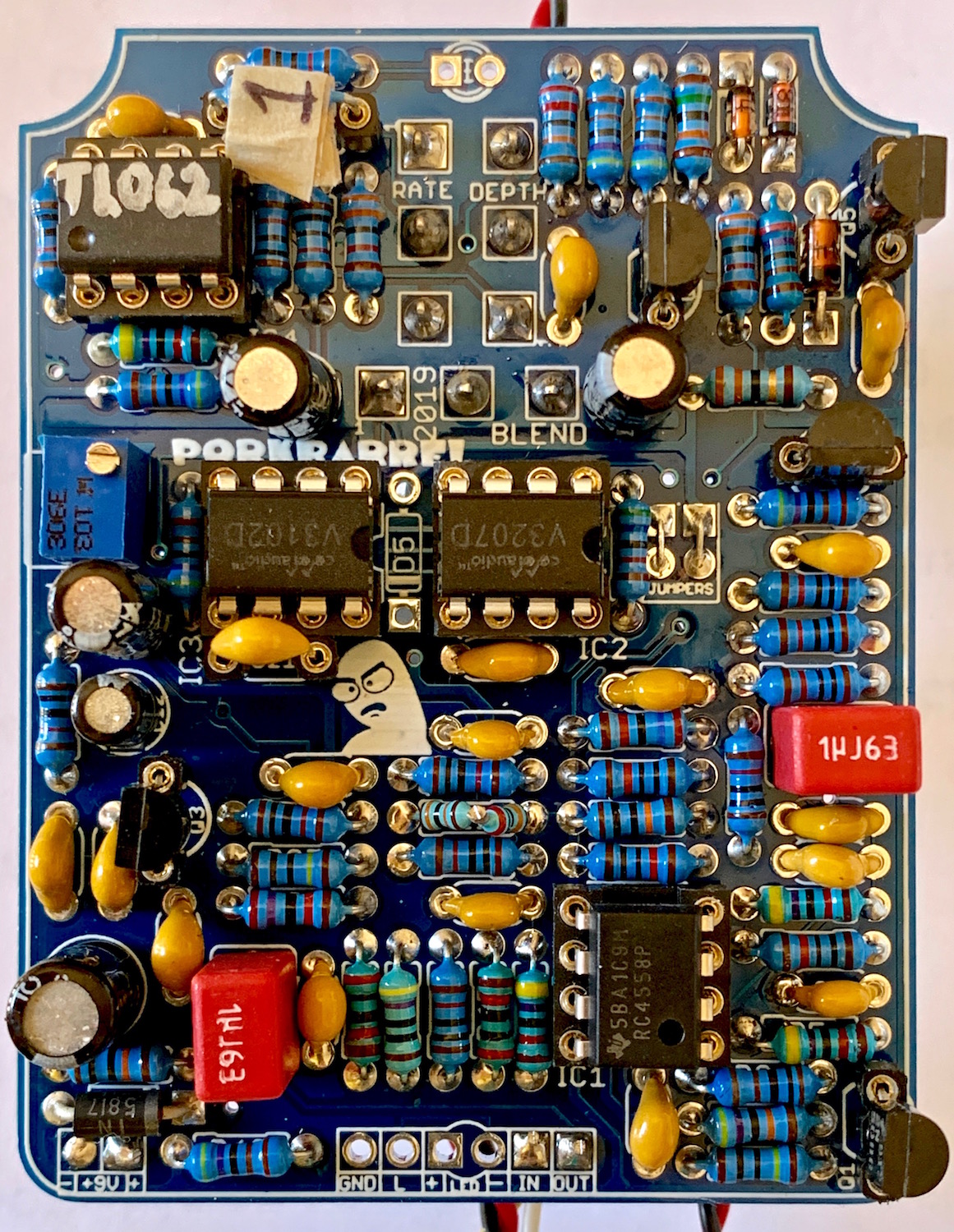
Just finished wiring up a Pork Barrel 2019 and have an issue I was hoping some kind soul may have encountered and can pass along a solution. Bypass works just fine. When engaged, I have to swing the "Blend" control all the way over to get any sound. The "Rate" LED pulses and changes speed with a change in the 'Rate' control - suggesting the LFO section is working as it should. I'm using the V3102 & V3207 clock and BBD combination.

As I adjust the trimmer towards one extreme, I can begin to hear some distorted sound and modulation, but no chorus effect.

All the voltages  - EXCEPT on the V3207 BBD are correct. Here are the voltages on the V3207 BBD:
1) 0.002 (effectively zero - supposed to be Vcc [9v])
2) 4.2 (seems to be correct)
3) 3.4 (supposed to be ~4.8)
4) 8.1 (supposed to be ~0.61)
5) 8.8 (supposed to be ~0)
6) 0.008(effectively zero)
7) 4.65 (seems to be correct)
8) 4.65 (seems to be correct)

I suspect a bad BBD, but would like to hear of any other insights or obvious blunders on my part.

I have NOT installed D5 (as per the build docs) and am using the vertical jumper configuration for the clock/BBD combo (also as per the build doc). All socketed devices are securely seated. All components acquired from SmallBear and\or Mouser.


Thank you for your time and consideration.
#9
General Questions / Softie Box Kit
July 25, 2020, 10:28:50 AM
I got a few of the Softie box kits while they were available and still have one left. (The ones I built are gone and I don't recall exactly how they behaved.) The question I have is: Is it JUST a bypass switch, or can it also be quickly double-tapped to go into non-lathing mode - like a momentary stomp. And then quickly double-tapped again to go back to regular latching mode? TIA
#10
This is photo-journal of building MadBean's "Harbinger 1.5" Uni-Vibe circuit PCB, done up in a 1590BB enclosure. (It's a long read, so you might want to get a cuppa before digging in. WARNING: Circuit Porn.) It can be built in either a standard 9v DC center negative construct, or the builder can opt for the 18v DC supply version. The details are in the build docs for this project.


I always start by first reading the build document a couple of times. (Familiarity is helpful.) Next, I ensure I already possess all the components as defined in the BOM; cross-checking with the 'shopping list' and examining the schematic. This takes a little more time, but ensures the build will go smoothly. Then I check the enclosure, PCB, and other hardware to see how easily things will fit once the guts are assembled. By loosely placing the PCB and hardware bits into the box in proximity of where they will most likely sit when finished, I then know I can proceed with the build with what I have.

To ensure the PCB mounted pots will wind up where they are supposed to go, I like to lay the PCB down into the enclosure and use a mechanical pencil to mark the borders. I'll also extend the lead of the mechanical pencil so I can mark where the center leg of each pot, switch and any LEDs will go. With the inside of the enclosure pencil-marked. I will then measure the distance of the pot legs to the pot center and add that distance to identify where the pot shaft and other holes should be drilled. I drill the pilot holes from inside the enclosure and afterwards, drill them to their respective proper sizes for hardware mounting. At this point, the enclosure is committed to the build.


Populating the PCB is the next step and I prefer to start with the lowest laying components first - the resistors. I place, solder and clip about a dozen resistors at a time. This minimizes the number of protruding leads than can interfere with soldering a PCB that has too many leg extensions sticking out here & there.


Next to populate are the larger, close-to-the-ground components like diodes, sockets and trimmers. Then onto film & ceramic caps and transistors. (In some cases, depending on the build, I socket transistors. But in this build, I'm a confident solderer and know the trannies being used are sturdy.) I populate electrolytic caps and special components last. In this case, the lamp, LDRs and shroud cap retaining legs are last. At this point, it's a good idea to flip the PCB over and apply a good bit of isopropyl alcohol and rub vigorously with an old toothbrush to clean off any excess flux.


With the PCB fully populated, I will the do a stuffing test by mounting the pots, LEDs and other hardware into the enclosure and squirreling the PCB onto the pot, switch & toggle legs. In so doing, I take careful note of how the PCB sits in the enclosure to see if it is higher on any one side than the other. Such un-even-ness often occurs on builds where there are both pots and toggle switches mounted to the PCB. Sometimes one is higher than the other. To get the PCB to rest level, I will use one of the toggle switch nuts to set the height (length) of the threads that will protrude thru the enclosure. Then I'll use a straightedge to check the level compared with the pots. Once the toggle switch adjustment nuts are set to the right depth, I hit them with a dab of nail polish to hold them in place for the duration of the build.


Knowing that everything fits properly, sits evenly and I've not burned any fingers or toes in the soldering process, I'll then commit the pots and toggle switches to solder on the PCB while the pots and toggles are fixed to the enclosure. Then, since everything is in place where it will sit when the build is complete, I start preparing the wiring by carefully measuring and place-testing each length of wire before cutting and stripping the ends. I then pre-bend each piece of wire re-test-fit it for loose precision.


Once all the wires have cut, stripped and bent to shape, I remove the guts and either replace them onto a cardboard version of the enclosure top or just wing it and start soldering the wires in small groups. On this build I started with the stompswitch because it has the largest 'group' of wires in one location. Then I went on to add the jack wiring. Here was a good spot to conduct a quick test to ensure the stompswitch and LEDs work, so I tack-soldered the DC jack on and fired it up to see if the worked properly. (This is that bit where you may or may not have heard to "rock it before you box it.") Yay! It works!


Meanwhile, during solder breaks or other interruptions, I would conjure up some artwork with Photoshop and get some waterslide decals printed out, clear-coated and dried.

After everything is wired, (except the DC jack, because it is soldered last after stuffing), the pedal gets another stuff-test and the DC jack gets soldered to the DC supply lines for the initial in-box test. Yay! It still works! But now, I have to remove the guts again so the enclosure can be finished. Heat up the soldering iron again, remove the DC jack, remove the guts and LED bezel and clean the enclosure with an 800 grit sand paper. Washed the enclosure with Dawn dish soap, rinsed thoroughly and let dry. (I used a blow dryer cuz my decals were ready to get laid.)


Final steps: apply the water slide, let dry a day, another half-dozen coats of clear, a dozen light coats of MinWax, re-stuff the guts and solder the DC jack, ensure everything is tight, fire up, test, adjust the offset and gain trimmers to taste, sign the bottom plate of the enclosure and close it up. Voila! It's a Vibe!


It's not even a neat or organized workspace. But it gets the job done. Thanks for reading.


Looks like a Pork Barrel (CE-2 circuit) build is on the horizon. Happy building!
#11
General Questions / Any Current Lover Mods?
July 15, 2020, 02:06:24 PM
About to embark on a Current Lover build. (Waiting for the new version.) Are there any known LFO mods for it? How slow can the Current Lover sweep go? When the new schematic is released, I'll have no problems identifying the LFO section. I'm just wondering if there is any experience with Current Lover mods anyone is willing to share. TIA
#12
With the now available release of X-Vive's MN3005, will the DirtBag Deluxe be considered for putting back on the available for purchase list?
#13
Build Reports / Cheese Fuzz (Sacred Cow prototype)
March 02, 2020, 01:32:17 PM
MadBean was kind enough to grant me one his "Sacred Cow" prototype PCBs and I finished it. I call it "Cheese Fuzz". A gnarly fuzz with a rotary selector for different tone shaping values and compression levels. It's based on the Big Cheese / JHS Cheesball fuzz. It's like a fuzz face wrapped in a op-amp and is capable of a high degree of compression/fuzz/ filtering. I retained the A10K volume pot instead of using MadBean's suggested A100K to better tame the output. Tried it out on a couple of solid state amps (cheese little Johnson 12 watt with a 6" speaker & a Line 6 Spider Jam 75 watt with a 12" speaker) and a tube amp (Vox MV50 AC with Marshall 4x12" cab) and it sounds great on all 3 amps. Anyway, here are some shots of the enclosure and a bit of circuit porn . . . . . .


Gut and build shots . . . .


#14
Build Reports / Triiiumvirate Build Completed
January 27, 2020, 12:06:36 PM
TRIIIUMVIRATE

Wrapped up my VFE-Triumvirate build this weekend. Having carefully pre-measured every component before committing it to solder, I didn't stop at the "rock it before you box it" step and proceeded directly to the "finish the enclosure, stuff it and fire it up" phase.

I was more pleased with what it does than surprised that it worked when I first fired it up. (I pre-measured all components before committing them to solder.) A 3-band distortion with this much control amongst the 3 separate bands is awesome! I excised no mods as the default build is a beautiful concept all by itself.


Really pleased with how the Gorva C65 enclosure takes waterslide decals. Then after two generous coats of Duplo rattle-can clear, a dozen light coats of MinWax make for decent protection.


The gutshot . . . .


I really wanted all 3 jacks top-mounted, so I had to get a little creative mounting them. I lost count how many times I measured the components and their respective relative distances and spacing. Got it down to 1mm tolerances. Still, I had to shave one of the jacks and its lock-washer.


Checking dimensions and PCB layout. Here's the component side of the boards.


Here's a shot of the solder side of the Triumvirate boards.


Stuffing test for decal testing in a Gorva C65 (125B style) enclosure.


Thanks for taking a peek!
#15
General Questions / Hunt for Very Thin Washers
January 25, 2020, 12:45:02 PM
I'm looking for these washers. I went to my local hardware store with no luck. I checked all the resource sites I have listed with no luck as well. LoveMySwitches has some similar, but the dimensions of his are not as good as these.

The dimensions are 20mm outer, 12mm inner and a=they are 0.5mm thick. I don't care if they are plastic, steel or aluminum. Any one?


I'm not sure from where this one came but it seems to be an oddball. But they are perfect for using with those large, bulbous colored aluminum stompswitch nuts. With those specific washers, I can bear down (tighten well) on those large stompswitch nuts without tearing into the water slide decal on the enclosure surface.
#16
VFE Projects / Triumvirate Build Doc Confusion
January 03, 2020, 04:58:20 PM
Just got the Triumvirate PCB and have a couple of questions regarding some of the instructions and parts regarding the "fixes".

1) The "10µF Cap Fix" - the text in the build doc says to use a non-polar 10µF, but the grayed PCB layout on page 7 shows the use of a polarized 10µF cap. (I understand that the grayed PCB layout is updated and does not match the PCB I received. And that's OK. I just want to better understand the 10 µF fix. The text says the cap was a late addition to prevent any DC offset from being amplified thru the bass section. I get that. But considering the cap (C20 ?) is connected between ground and the 1K resistor (R4), it seems to me that a standard polarized electrolytic can be used with the negative leg connected to ground and the positive side connected to the 1K resistor. Also, the Shopping List on page 3 states in bold that the 10µF cap does not have to be bi-polar (NP). I'd just like to be clear on this point.

2) The suggested mod for the Treble Band Distortion - (not so much of question, rather a gripe) - this mod refers to R11 & C14. While locating R11 & C14 on the schematic is easy enough, locating them on the PCB requires some circuit tracing to locate. I could not see any obvious means of identifying R11 & C14 otherwise.

3) All of the 0.1µF MLCC cap locations are marked as "PWR" on the silkscreen. I found that rather confusing till I sorted it out thru the PCB layout image on the first page of the build doc.

Other than my whiny rants, this is a circuit I've been looking forward to building for a while now and truly appreciate all the great effort that went into creating the PCB and build docs. The mods are impressively noteworthy as well. I considered adding toggle switches to the clipping diodes in each section, but with space at such a premium in a 125B sized enclosure, I shall wait to do that in a second Triumvirate build in a larger enclosure and not mount the pots to the board.

Thanks for reading.
#17
VFE Projects / VFE Triumvirate PCB Restock ETA? [SOLVED]
November 25, 2019, 12:39:10 PM
I'm looking forward to doing a VFE Triumvirate. Any idea on when they might be back in stock?

Ordered and received !
#18
General Questions / LaserWolf Order Switch Pad Jumpers
August 30, 2017, 01:49:58 PM
If I've done my homework right, I should be able to configure the order switch-pads on the LaserWolf to get an OverDrive - Phaser - Delay circuit order using the connections indicated in the attached image. I' just looking for another set of LaserWolf-aware eyes to verify. tia