News:

Forum may be experiencing issues.

Main Menu
Menu

Show posts

This section allows you to view all posts made by this member. Note that you can only see posts made in areas you currently have access to.

Show posts Menu

Messages - youngstownguitar

#31
Tech Help - Projects Page / Re: basic PCB question
January 08, 2011, 08:38:11 PM
great

now i can solder with confidence

thanks
#32
Tech Help - Projects Page / Re: basic PCB question
January 08, 2011, 10:57:17 AM
Thanks a lot.  Sorry for the stupid question.  I just would have hated to have wired everything backwards
#33
Tech Help - Projects Page / Re: basic PCB question
January 08, 2011, 10:49:08 AM
Sure. 


On the left is the zombii with the written side up- what is the actual term for this? The etched side?
On the left is the slambox with the written side down.

I am concerned because as you see the pots I have are board mounted.  If I wire everything on the wrong side they will all be backwards right?  I think the pots and the components should be on the black side and the solder on the etched side- am I right?
#34
Tech Help - Projects Page / Re: basic PCB question
January 08, 2011, 09:16:44 AM
Ok I guess my real question is:  Are the layouts and PCBs intended for the solder on the black side or on the written side?  I just dont want to accidentally do it backwards and have all my transistors and pots reversed.
#35
Tech Help - Projects Page / Re: basic PCB question
January 07, 2011, 09:00:06 PM
Great

So I will put the components on the black side and the solder on the traced side.  

I wont reverse any transistors or pots or anything then- right?
#36
Tech Help - Projects Page / basic PCB question
January 07, 2011, 07:36:44 PM
I have a couple madbean PCBs here.  A zombii V.4 and slambox V.3.  The PCBs are just black on one side while the other side has writing.
Does it matter which side gets soldered?  I have looked at other builds here and it seems that all of them have the components on the writing side and the solder on the black side- but I would Like to do it backwards.  Would this work or is there a rule?

Thanks!
#37
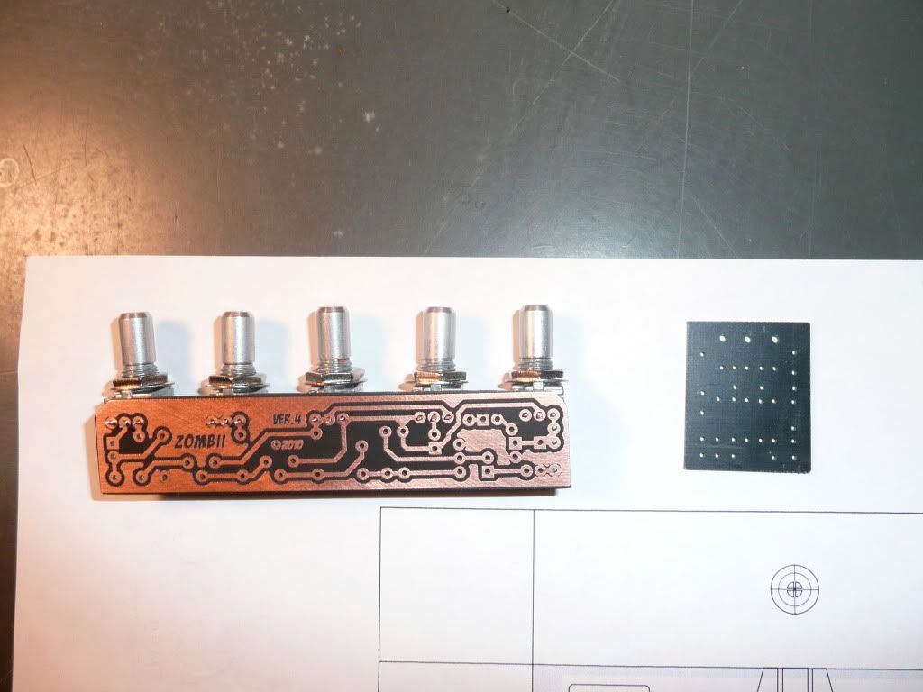
Quote from: madbean on December 14, 2010, 02:18:02 PM
That's right. The CLR is on the board for this particular one (Slambox & Zombii).


Thanks again!
#38
I cant thank you enough.

So that explains offboard wiring.  If you want to just use the spot on the board then there is no need to add resistor right?

very very helpful- thanks
#40
Thanks for the warning madbean (and for checking the diagram) but I think Im gonna go ahead with this project anyway.  If its too loud then I will just run them separate.  I think it will still be cool to have them together.

I am still trying to understand the LEDs...

If I use the LED spots on the PCBs which end is positive? The rounded or flat side?

And for that matter, how does the LED work?  I know that one end is longer than the other and that signifies the voltage but I cant find which one is positive and which is negative.

If I dont use the LED spots on the PCBs could I wire it like this...
For the Zombii: Bottom left spot of switch - to LED - to 5k resistor - to DC jack
For the Slambox: Bottom left spot of witch - to LED - to 5k resistor- to 9v spot in PCB
I used this diagram to figure this out:
http://www.generalguitargadgets.com/pdf/two_in_one_wiring.pdf


And finally... I dont want to even deal with a battery- I never use them.  Can I just erase it from the diagram or do I need to change the circuit around?

Thanks again.  I feel stupid asking all these questions.  I really did spend hours last night researching this stuff.  I learned a lot but I couldn't figure these couple things out for sure.
#41
great- thanks a lot
everything I found was so much more complicated than that
#42
OK 2 more questions...

I see for the Zombii v4 trannies madbean says "• Stock unit originally used AC128s. Any PNP GE transistors with appropriate gain ranges will suffice. Suggested Hfe for Q2 is
around 70 and for Q3 around 110. "

What would be a good way of finding appropriate transistors for this?
Here is smallbears transistor list:
http://www.smallbearelec.com/Categories.bok?category=Germanium+Transistors
Would the second or third set down work?

And finally, I am confused about the resistors that are needed with LEDs.  I found some calculators for it but I dont even know enough to figure out how to work the calculator.
This is the LED I was planning on using:
http://www.smallbearelec.com/Detail.bok?no=333

What resistor should I use and would it be the same for the zombii and the slambox?

I think that may be the last of my questions- yea right...
#43
The Slambox v.3 calls for a "9V Zener" for D2.

On smallbear I can only find "9.1V 1 watt"

http://www.smallbearelec.com/Categories.bok
its the 5th one down

Is this the right one?
#44
wow
thanks for all the info so far guys

I am at work now but later tonight I will sit down and make a complete parts list and post it here along with any other questions I can think of.

Thanks again.
#45
Hello
I am planning on putting a zombie and slambox into one enclosure, the zombii coming first.  I dont have a lot of experience with building but I do enjoy it very much.  So far I have only one build under my belt and it is a GGG fuzzface.  This being my first build that is not from a kit I have some questions that I hope someone would help me with please.  I am a nerd so I am going to number the questions.  I have tried researching all of this stuff beforehand- a lot of it is just things I am not 100% sure of- and I'd hate to have it ruin my build.

1.  I was planning on buying some #22 gauge wire- this is acceptable right?  If i buy this wire what size shrink tube should I get?

2.  What do you guys put on the side of the PCB with all the solder on it?  I have seen some people just put electrical tape but is that ok?  What is best?

3.  Here is my parts list so far (from smallbear), does it look right?
    I found the LED but not a holder for the LED- anyone know where that is or does it come with it?
    The slambox uses a reverse audio pot right?

   0301A    Box - Taiwanese 'BB' Size White Powder Coat  ('BB' White)    $9.95   $9.95

   0508C    Wire, #22 Pre-Bond, 50 Ft. Sampler  $6.75   $6.75

   2302    LED T-1 3/4 5mm Water-clear High-brightness (White)    $0.50   $1.00

   0611    Jack, DC Power, 2.1 mm All-Plastic, Round (All-plastic Round)    $1.25   $1.25

   0600    Jack, 1/4 in. Mono Switchcraft #11  (#11)    $1.85   $1.85

   0602    Jack, 1/4 in. Stereo Switchcraft #12B (#12B)    $1.89   $1.89

   0200    Switch - Taiwan Blue 3PDT (Blue 3PDT)    $8.50   $8.50

   1001    Alpha Single-Gang 24mm, Linear & Audio Taper, Solder Terms (5K Linear)    $1.25   $2.50

   1001    Alpha Single-Gang 24mm, Linear & Audio Taper, Solder Terms  (10K Linear)    $1.25   $3.75

   1007    Alpha 16mm Single-Gang, Reverse Audio & "W", Solder Terms  (5K)

4.  Absent from my parts list are my resistors and capacitors.  How do you know what type of capacitor to use?  It seems to me that some of them can be the same values but different types- am I wrong?  I need clarification please.

5.  To put both effects in order in one enclosure I used this wiring diagram:
     http://www.generalguitargadgets.com/pdf/two_in_one_wiring.pdf
    But it does not fit perfectly with everything so I drew my own diagram out (I apologize but I could not figure it out on my computer so I just hand drew it with some markers and scanned it).
   Do you think it would work like this?

If the pic is hard to see there it can also be found here:
http://s640.photobucket.com/albums/uu130/surgerymixer/?action=view&current=goatlegdrawing.jpg


Thanks in advance for any info anyone could spare.  I tried to be clear with my questions.