News:

Forum may be experiencing issues.

Main Menu
Menu

Show posts

This section allows you to view all posts made by this member. Note that you can only see posts made in areas you currently have access to.

Show posts Menu

Topics - rmfroyd

#1
Open Discussion / Found a U.S. Powdercoater
November 11, 2019, 11:17:13 AM
https://www.modzbynasy.com/

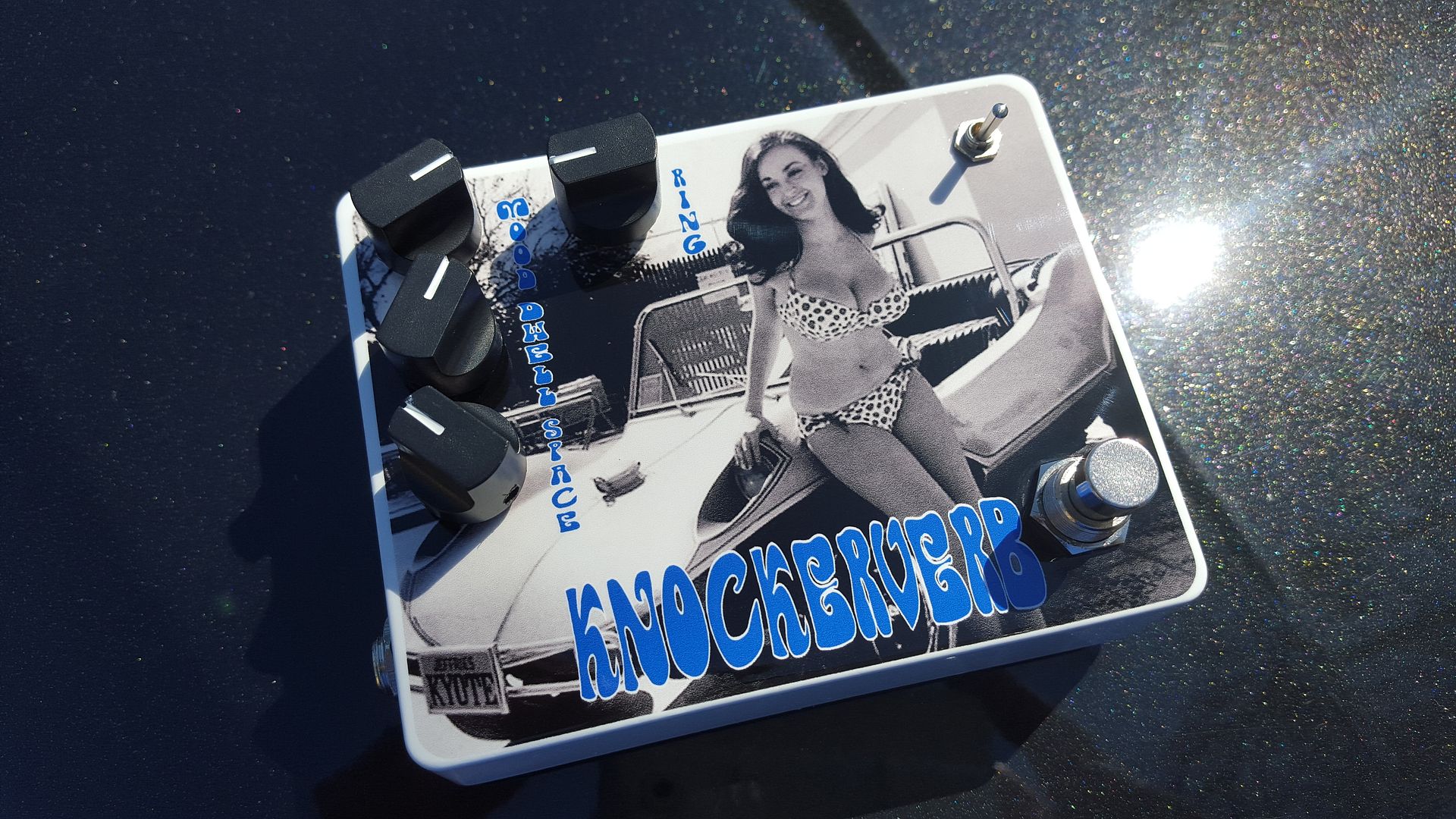
He did this box for me:


His boxes are kinda pricey but the powder-coating is only $5.  Right now he stocks 1590bb, but should be getting some 125b's in shortly.  Cool guy, fast turnaround.  Might be able to get him to stock more stuff as well, he seemed to be open to the idea.

Now that Mammoth is gone/in-limbo, I am not sure where else you can get one-off boxes. 
#2
Tech Help - Projects Page / continuing lowrider problems
December 19, 2018, 06:43:22 PM
I need a Christmas Miracle....

Had problems with the first board I bought.  They all started with IC5, specifically the Voltages at pin 8 and pin 14.  I would measure the voltage at pin 14 and it would be correct.  Measure at pin 13, correct, go back and measure at pin 14  and voltage was down about 5 volts. Went through about 10 %$^&in IC's same result.  Bought new ones, same result.

Put myself in a time out for a couple weeks, and I bought a new board.  Populated it, and I am still having problems at pin 8 and pin 14.  Brand new IC's.  This time the voltage is fluctating on both pins between 5 and 6 on pin 14 and between 1.5 and .003 on pin 8.  All new IC's, all resistors check out, reflowed solder eleventyhundred times....

I have built over 100 boards and I have never failed this badly.  Is there a chance it is a bad batch of PCB's?  Has anyone built one in the last 6 months that has worked?

Thanks for taking the time.
#3
Tech Help - Projects Page / Lowrider Schematic Question
October 25, 2018, 05:55:00 AM
I am still having problems with my lowrider board.  My voltages on IC7 are off, pin 12 and pin 13 are wrong

Correct Voltage from Build Doc
Pin 12 9.1
Pin 13 0

My voltage
Pin 12 0
Pin 13 9.1

So whatever is driving my flip to flop in the 2nd flip flop of the 4013, is neither flipping nor flopping it.

When I look at the schematic  IC7B is off by its little old self, does that mean it is irrelevant to the circuit?

#4
General Questions / Mic to pedal/pedal to mixer
October 15, 2018, 09:51:50 AM
I have a buddy that wants me to make a custom pedal for him, he play saxophone and sings in a band.

Here is what he would like

XLR in>>>>Delay Pedal>>>>>>Wah>>>>XLR out.

So, the XLR in is coming in balanced, I hook up pin 1 of the XLR jack to ground, and pin 2 of the xlr jack to input.  Now the signal is unbalanced.  It goes through the delay and wah and then if I build a H&K redbox classic circuit, it should then convert that signal from unbalanced to balanced and everything can go to the mixer board like it is supposed to correct?

#5
Tech Help - Projects Page / Lowrider IC5 voltages
September 23, 2018, 04:06:25 PM
I need some schooling please.

Ic5 on the lowrider is a LM324.  My voltages at pin 8 and pin 14 are whack.

Pin 8=-5.4mv
Pin 14=1.19 v

according to the build doc they should be:

pin 8=2.2 mv
Pin 14=7.9 v

What I don't understand,(and my knowledge is limited on pretty much everything)  is that according to the pinouts pin 9 and 10 feed pin 8, and pin 12 and 13 feed pin 14.

Is if my voltages are correct at 9 and 10 as well as 12 and 13, how can the chip be feeding me the wrong voltages?

Or am I completely off the mark?

Thanks for your help.
#6
Build Reports / DBA EchoDream 2
April 30, 2017, 11:00:17 AM
This one was a lot of offboard wiring...too much.  Glad it worked.  Cool stuff but too much for me.


Sent from my SM-G920V using Tapatalk

#7
Build Reports / 1590 Gs
January 22, 2017, 12:21:01 PM
Finally finished these up.  Fun builds, but man, I am ready to build something with a little extra room in the enclosure.  All sound great, I really like the vibe.


And the last one that went to a friend a few weeks ago:


Thanks for some great boards and a great project.

#8
General Questions / Peavey Classic 30 Footswitch Help
December 17, 2016, 10:35:17 AM
My friend told me his is getting a Classic 30 for Christmas, so I decided to surprise him with a footswitch.  Got it all built up and I am having a few problems.  My main problem being that the closest classic 30 to test with is 20 minutes away at a local Sam Ash.  I have already been there twice today, and I am still not having any luck.

Here is a pic:


I have been using this schematic(I found it on the internet, so it has to be right.....)


From Left to Right:  Reverb, Boost, Channel.

Problems.

Reverb switching works, but LED lights when off, and turns off when on.

Middle Lug to sleeve, top lug to 100k resistor to positive side of LED. Negative side of LED to tip

Boost switching works perfectly, not problem there

Middle lug to sleeve, top lug to 100k resistor to positive side of LED.  Negative side of LED to Tip on Stereo Jack

Channel switch works not at all.  Led works fine, but channels don't switch

Middle lug to sleeve, to lug to 100k resistor to positive side of LED.  Negative side of LED to Ring on Stereo Jack.

Any help would be greatly appreciated, and yes, I am using a stereo cable.

Thanks for looking.


#9
I have been searching with the google machine most of the morning and have come up empty.

Here is what I would like to do:

Autowah and Fixed(cocked)wah in same enclosure.

1 footswitch to turn Autowah on or off, wLED
1 footswitch that turns off autowah, turns on Fixed wah, for ripping cocked wah like solo.  also w LED

I found plenty of diagrams on how to wire up to circuits with the ability to blend together, but I haven't been able to find any where you can turn one off and one on with one footswitch yet.

Thanks in advance for your help.
#10
Build Reports / 3 more all built up and stuff
March 24, 2016, 05:06:05 AM
Collosalus.  This build almost killed me.  Went through two boards before I got it to work.  Sounds great, didn't think I had much use for a Flanger.  This one changed my mind.


GuitarPCB Dr. Phybes.  I redid the Led lighting on this one to get it a bit brighter.


Skyrim inspired Proco Rat.  Machined the circuit for this.  Got the layout from storyboardists website.


#11
Open Discussion / Pot Height
March 22, 2016, 07:36:45 AM
I am trying to machine up some PCB standoffs for PCBs that don't have board mounted pots.  I really don't much like having them hang in space by their wires. 

I have made ones for boards where the pots don't interfere with the board, but would like to make some for boards that sit over the Pots. 

In my forgetfullness, I forgot to take some measurements this morning before I left for work.  Could one of you measuer how far the back of the pot sticks up inside the enclosure?

Thanks in advance!
#12
Build Reports / A few new builds
February 29, 2016, 09:38:46 AM
Well, after the debacle that was my attempted Collosalus build, I need my ego fed....

First up is a Mood Ring.  Fun build and sounds awesome.  Always nice when they work first shot:


Next up is a 2 knob Acapulco Gold.  I etched the board for this one myself.


PHase 90 GUitar PCB


Aion DS-1


Guitar PCB Animal(G2 CLone)


Thanks for looking.  I gotta get better at taking pictures of the internals.  I always forget.
#13
Tech Help - Projects Page / Collosalus (I am failure)
February 22, 2016, 04:53:54 AM
I have been trying to troubleshoot a 2015 Collosalus board that isn't working.  I am going to get in depth with the troubleshooting tonight, but I had a quick question for you people.

Has anyone run into a 1N5817 that is literally burning hot to the touch?  I was going through the build and actually touched it this morning, and about burned my dang finger.

It is D3, on the build document.  I am doing the 18volt mod.  Could it be a bad Diode, or something before, and or after that Diode in the circuit?

Thanks for all your help in advance.