• Welcome to madbeanpedals::forum.

News:

Forum may be experiencing issues.

Main Menu
Menu

Show posts

This section allows you to view all posts made by this member. Note that you can only see posts made in areas you currently have access to.

Show posts Menu

Messages - Cybercow

#31
Bench update . . . .

With the TLE2074 removed:
1) pins 12 & 13 now read 4.88 volts - but pin 1 reads only 1.2v.
2) unable to measure the 2M2Ω resistor between pins #12 & #5 of the socket - but there is continuity between pin 12 and the 2M2Ω resistor; there is also continuity between pin 5 and VB - AND continuity between the other side of the 2M2Ω resistor and VB.
3) the 2M2Ω resistor measures 2.2M Ω (with the TLE2072 out of the socket.

On the SB3 board:
1) R5 & R6 are in place
2) C6 is installed reverse of the PCB markings (as per the build doc)
3) there is ~4.88 volts on the V- point and ~9v on the V+ point

Other points:
1) all 3 16mm pots have SmallBear pot condoms on them
2) with all chips in place, powered up and plugged in, all the controls have functionality. The output is just quite distorted. (The first opamp [TLE2074] section has a low-voltage condition on pins 12, 13 & 14.)
3) C18 (.22µF) is not leaky (from Mouser)
4) C12 (10µF BP) is not leaky (from Mouser)
5) Tried a few different quad opamps (TL074, TL084, OPA4134 & OPA4132) and all exhibit the same low voltage on pins 12, 13 & 14 - and all the pots still have functionality - just dirty output
6) With all chips in place and the circuit powered up, there is 4.88v at the VB points, including pin 5 of the TLE2074

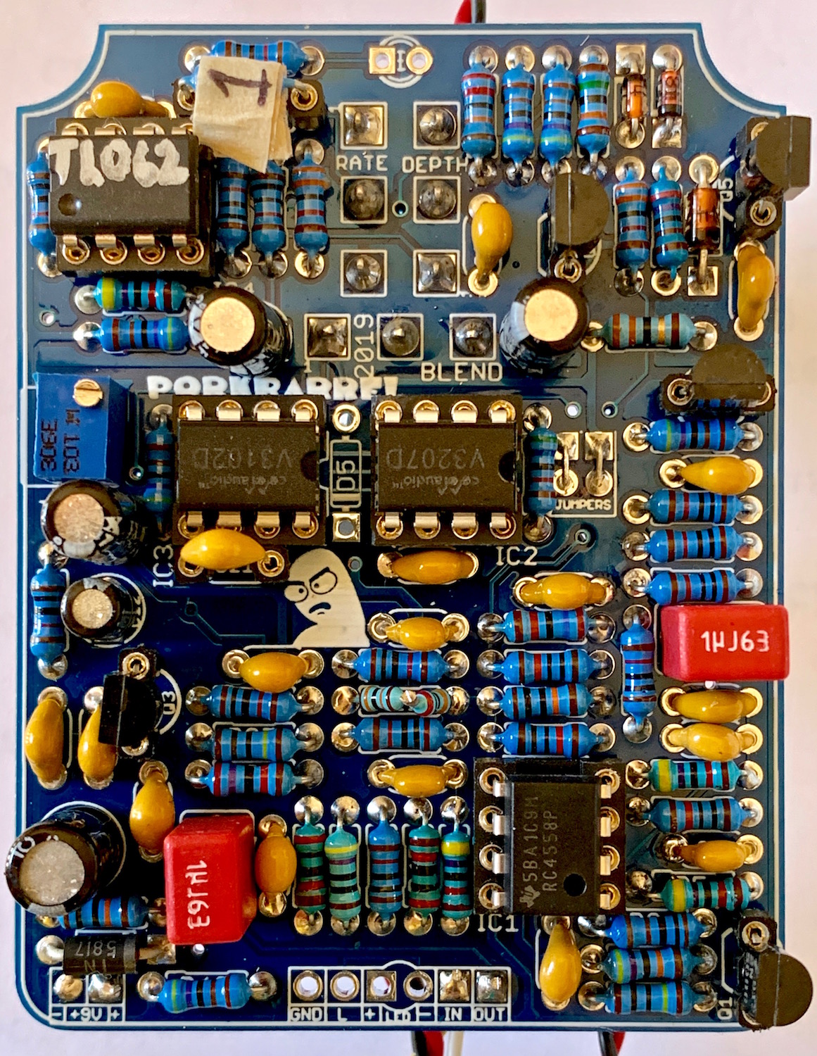
I've not started pulling my hair out yet, but it's close to that pointless prospect. Clear photos coming shortly.

Any further suggestions or things to check will be appreciated.
#32
Quote from: danfrank on August 06, 2020, 04:37:20 PM
Did you add the 2 resistors and reverse the one cap on the switching board? This is part of the "choral reef" difference on the switching board.

Yes - R5 & R6 installed and C6 installed reverse of the polarity markings on the SB3.
#33
Quote from: Scruffie on August 06, 2020, 03:21:08 PM
That'll do it, I was expecting that the BBD output op amp was going to be the problem, given how close to the rails it ends up biased.

What doesn't make sense is why all the other voltages are correct. I even swapped the TLE2074 with a fresh one - same result. (I got both TLE2074 chips from Mouser, so I should be able to assume they're both good. Or at least one of them.)

I'll look closer at the SB3 switching board to see what I can find. Without a schematic for it, I'm left to tracing from the layouts in the SB3 build doc. And I did catch the bits in that build that are exclusive to the Choral Reef.

Back to the bench . . .. .
#34
Quote from: madbean on August 06, 2020, 03:15:42 PM
Remember that for the Choral Reef the VB source is on the switching board. This is explained in the SB3 doc. It's the only project that requires it.

I just sorted that bit out. And I did carry over the -V line from the SB3 to the PCB. I also followed the explicit instructions in the "In the Choral Reef the following exceptions are applied" section, leaving off the charge pump IC and C5.
#35
Quote from: Scruffie on August 06, 2020, 10:16:04 AM
What sort of pickups are you using? It's not exactly designed for high headroom.

Could you please also post your MN3008 voltages regardless, just so I can double check them.

Thanks Scruffie . . . . I use a '79 Strat, so the pups are not hot. I remeasured all the voltages as shown in the chart, and the MN3008 is spot on. However, I think I've found the source of the distortion.  Pins 12, 13 & 14 of the TLE2074 are reading much lower than they ought. Instead reading 3.86, 4.88 & 4.88 respectively, they are at 0.93, 1.04 & 1.04 - also respectively to pins 12, 13 & 14 of the TLE2074. That's the first opamp section in the circuit. All other voltages are within 5% of the voltages listed in the build doc. Except pin 2 of the 4047 which measures 34mV instead of 115-118mV.

When I try to measure the 2.2MΩ resistor on pin 12 of the TLE2074 (with the TLE2074 removed) I cannot get a reading between pin 12 and the VB. Theoretically, with the TLE2074 removed, I should be able to read 2M2Ω between pins 12 and 5 on the TLE2074 socket. But it reads as 'open'.

Also, there seems to be no source of "VB" on the schematic and as such I have no reference for what VB is supposed to be. I can only guess it's supposed to be 1/2 of the supply voltage. I can easily find 4 locations on the schematic where "VB" connects to specify points, but no reference to a "VB" in the power distribution section.
#36
Got the Choral Reef up and running today but I cannot seem to ditch the distortion. All the voltage measurements seem to match the build document voltages. And I've gone back and forth between the two trimmers to try and get rid of the distortion. No parts substitutions - except that 65K resistor where I tented two resistors that equal 65K in series.

I followed the build docs for adjusting the BBD, but it sounds very distorted. There is a sweet spot at just about midway on the BBD trimmer where the distortion is at a minimum. But I don't believe it should be that distorted.

All parts were sourced from SmallBear and Mouser.

Does anyone have any experience with the VFE Choral Reef that has a distorted output? Or are the trimpots just that fussy with only a tiny sweep section of each of the trimmers? I spent over an hour already futzing with them in very tiny increments.

TIA
#37
Just finished wiring up a Pork Barrel 2019 and have an issue I was hoping some kind soul may have encountered and can pass along a solution. Bypass works just fine. When engaged, I have to swing the "Blend" control all the way over to get any sound. The "Rate" LED pulses and changes speed with a change in the 'Rate' control - suggesting the LFO section is working as it should. I'm using the V3102 & V3207 clock and BBD combination.

As I adjust the trimmer towards one extreme, I can begin to hear some distorted sound and modulation, but no chorus effect.

All the voltages  - EXCEPT on the V3207 BBD are correct. Here are the voltages on the V3207 BBD:
1) 0.002 (effectively zero - supposed to be Vcc [9v])
2) 4.2 (seems to be correct)
3) 3.4 (supposed to be ~4.8)
4) 8.1 (supposed to be ~0.61)
5) 8.8 (supposed to be ~0)
6) 0.008(effectively zero)
7) 4.65 (seems to be correct)
8) 4.65 (seems to be correct)

I suspect a bad BBD, but would like to hear of any other insights or obvious blunders on my part.

I have NOT installed D5 (as per the build docs) and am using the vertical jumper configuration for the clock/BBD combo (also as per the build doc). All socketed devices are securely seated. All components acquired from SmallBear and\or Mouser.


Thank you for your time and consideration.
#38
General Questions / Softie Box Kit
July 25, 2020, 05:28:50 PM
I got a few of the Softie box kits while they were available and still have one left. (The ones I built are gone and I don't recall exactly how they behaved.) The question I have is: Is it JUST a bypass switch, or can it also be quickly double-tapped to go into non-lathing mode - like a momentary stomp. And then quickly double-tapped again to go back to regular latching mode? TIA
#39
Build Reports / Re: VFE Bumblebee
July 19, 2020, 04:11:21 PM
Quote from: jimilee on July 19, 2020, 03:49:18 PM
Quote from: Cybercow on July 19, 2020, 03:39:54 PM
JimiLee - so glad you finally got it working. Looks great!
Thank you. You gotta have the right 5457. It was affecting the voltage and I dont'know why. It was a bear, that's for sure.

JimiLee - FETs are a fickle device. Kinda like NOS germanium trannies in that the specs can be all over the map for any given part number. When ever applying FETs, I always socket them because it can be a crap shoot selecting them. Even with a Peak Atlas DCA75 to pre-test (measure) them, they can be fickle. Still, happy to see this done.

How do you like it? Is the swell dramatic or  . . . . . ?????
#40
Build Reports / Re: VFE Bumblebee
July 19, 2020, 03:39:54 PM
JimiLee - so glad you finally got it working. Looks great!
#41
Quote from: jimilee on July 18, 2020, 11:15:30 PM
Thank you for the photo essay. That's looks fantastic, and that soldering iron. I spent 12.00 on one just like it. It was supposed to be temporary if I liked the hobby. I used it for 8 years. It still works great, I just replaced it because I wanted a nicer one. I still use it from time to time.

Thanks JimiLee. I've had that cheap little soldering iron for 4 years now and had to replace the wand a couple month ago. It's quite inexpensive, as you've noted, and has a number of tips to change out. The replacement wand was only 4 zorkmids.
#42
Quote from: lars on July 18, 2020, 10:32:26 PM
Very professional build and detailed process. The part that interested me the most is that tiny and perfectly executed LED indicator next to the Intensity control. It's so flush and unobtrusive you almost don't see it (which is the point). Well done.

Thanks!  I'll admit that I took a little extra time on the rate LED. I intentionally drilled the hole too small, then slowly with a hand-reamer kept digging at it, bit-by-bit to get it just right so just the dome was peeking thru the top. Then I used fine-mill file to flatten the LED till it sat flush in the tight hole.
#43
Quote from: Bio77 on July 19, 2020, 12:52:23 AM
Beautiful build!  Top shelf. The solder joints on the resistors are perfect.  Do you flow through the bottom just right, or touch up on the top?

Thanks! I start soldering from the bottom and touch-up on top after inspection reveals a need.
#44
Build Reports / Re: Tourbillion Phaser
July 18, 2020, 08:48:28 PM
Great etching work Jimilee!
#45
This is photo-journal of building MadBean's "Harbinger 1.5" Uni-Vibe circuit PCB, done up in a 1590BB enclosure. (It's a long read, so you might want to get a cuppa before digging in. WARNING: Circuit Porn.) It can be built in either a standard 9v DC center negative construct, or the builder can opt for the 18v DC supply version. The details are in the build docs for this project.


I always start by first reading the build document a couple of times. (Familiarity is helpful.) Next, I ensure I already possess all the components as defined in the BOM; cross-checking with the 'shopping list' and examining the schematic. This takes a little more time, but ensures the build will go smoothly. Then I check the enclosure, PCB, and other hardware to see how easily things will fit once the guts are assembled. By loosely placing the PCB and hardware bits into the box in proximity of where they will most likely sit when finished, I then know I can proceed with the build with what I have.

To ensure the PCB mounted pots will wind up where they are supposed to go, I like to lay the PCB down into the enclosure and use a mechanical pencil to mark the borders. I'll also extend the lead of the mechanical pencil so I can mark where the center leg of each pot, switch and any LEDs will go. With the inside of the enclosure pencil-marked. I will then measure the distance of the pot legs to the pot center and add that distance to identify where the pot shaft and other holes should be drilled. I drill the pilot holes from inside the enclosure and afterwards, drill them to their respective proper sizes for hardware mounting. At this point, the enclosure is committed to the build.


Populating the PCB is the next step and I prefer to start with the lowest laying components first - the resistors. I place, solder and clip about a dozen resistors at a time. This minimizes the number of protruding leads than can interfere with soldering a PCB that has too many leg extensions sticking out here & there.


Next to populate are the larger, close-to-the-ground components like diodes, sockets and trimmers. Then onto film & ceramic caps and transistors. (In some cases, depending on the build, I socket transistors. But in this build, I'm a confident solderer and know the trannies being used are sturdy.) I populate electrolytic caps and special components last. In this case, the lamp, LDRs and shroud cap retaining legs are last. At this point, it's a good idea to flip the PCB over and apply a good bit of isopropyl alcohol and rub vigorously with an old toothbrush to clean off any excess flux.


With the PCB fully populated, I will the do a stuffing test by mounting the pots, LEDs and other hardware into the enclosure and squirreling the PCB onto the pot, switch & toggle legs. In so doing, I take careful note of how the PCB sits in the enclosure to see if it is higher on any one side than the other. Such un-even-ness often occurs on builds where there are both pots and toggle switches mounted to the PCB. Sometimes one is higher than the other. To get the PCB to rest level, I will use one of the toggle switch nuts to set the height (length) of the threads that will protrude thru the enclosure. Then I'll use a straightedge to check the level compared with the pots. Once the toggle switch adjustment nuts are set to the right depth, I hit them with a dab of nail polish to hold them in place for the duration of the build.


Knowing that everything fits properly, sits evenly and I've not burned any fingers or toes in the soldering process, I'll then commit the pots and toggle switches to solder on the PCB while the pots and toggles are fixed to the enclosure. Then, since everything is in place where it will sit when the build is complete, I start preparing the wiring by carefully measuring and place-testing each length of wire before cutting and stripping the ends. I then pre-bend each piece of wire re-test-fit it for loose precision.


Once all the wires have cut, stripped and bent to shape, I remove the guts and either replace them onto a cardboard version of the enclosure top or just wing it and start soldering the wires in small groups. On this build I started with the stompswitch because it has the largest 'group' of wires in one location. Then I went on to add the jack wiring. Here was a good spot to conduct a quick test to ensure the stompswitch and LEDs work, so I tack-soldered the DC jack on and fired it up to see if the worked properly. (This is that bit where you may or may not have heard to "rock it before you box it.") Yay! It works!


Meanwhile, during solder breaks or other interruptions, I would conjure up some artwork with Photoshop and get some waterslide decals printed out, clear-coated and dried.

After everything is wired, (except the DC jack, because it is soldered last after stuffing), the pedal gets another stuff-test and the DC jack gets soldered to the DC supply lines for the initial in-box test. Yay! It still works! But now, I have to remove the guts again so the enclosure can be finished. Heat up the soldering iron again, remove the DC jack, remove the guts and LED bezel and clean the enclosure with an 800 grit sand paper. Washed the enclosure with Dawn dish soap, rinsed thoroughly and let dry. (I used a blow dryer cuz my decals were ready to get laid.)


Final steps: apply the water slide, let dry a day, another half-dozen coats of clear, a dozen light coats of MinWax, re-stuff the guts and solder the DC jack, ensure everything is tight, fire up, test, adjust the offset and gain trimmers to taste, sign the bottom plate of the enclosure and close it up. Voila! It's a Vibe!


It's not even a neat or organized workspace. But it gets the job done. Thanks for reading.


Looks like a Pork Barrel (CE-2 circuit) build is on the horizon. Happy building!